
Image: CRC-32 Algorithm Overview Diagram
Published: January 9, 2026 at 10:07:35 PM UTC
Last updated: January 9, 2026 at 10:08:00 PM UTC
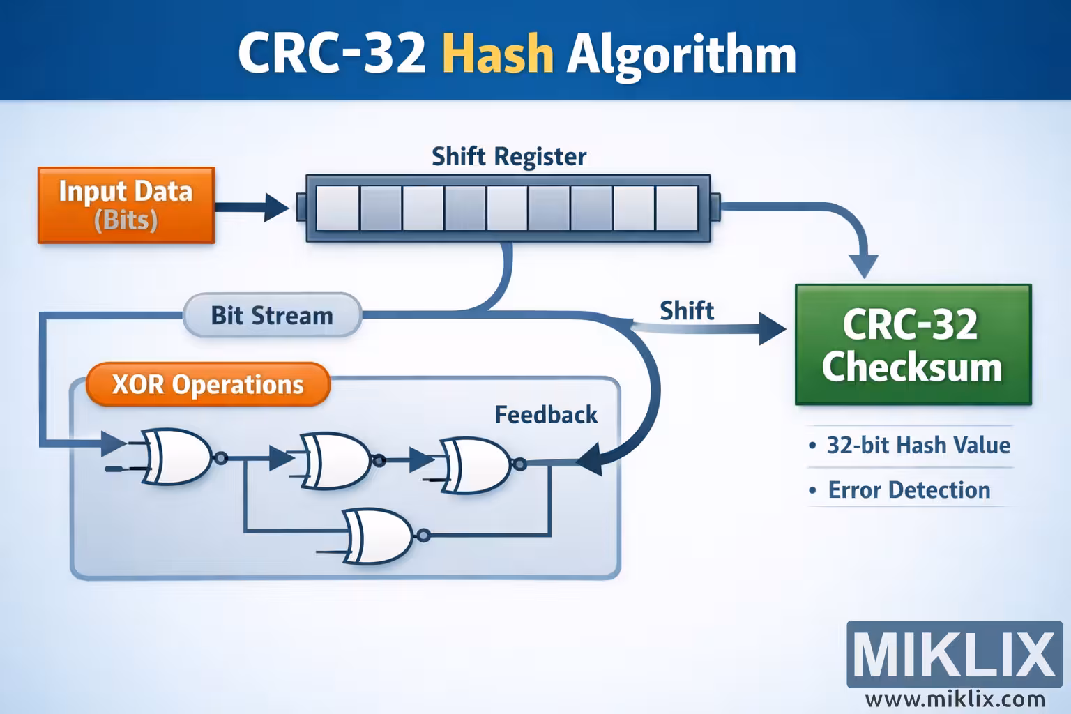
Educational visualization of the CRC-32 hash algorithm, illustrating how input bits flow through a shift register with XOR feedback to generate a checksum.

Available versions of this image
The image files available for download below are less compressed and higher resolution - and as a result of that, higher quality - than the images embedded in articles and pages on this website, which are more optimized for file size in order to reduce bandwidth consumption.
Regular size (1,536 x 1,024)
Large size (3,072 x 2,048)
Very large size (4,608 x 3,072)
Extra large size (6,144 x 4,096)
Comically large size (1,048,576 x 699,051)
- Still uploading... ;-)
Image description
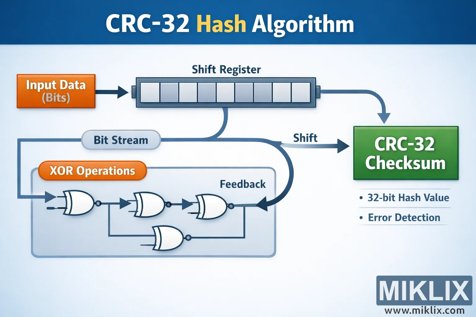
The image is a wide, landscape-oriented educational diagram titled "CRC-32 Hash Algorithm" set on a clean, light background with a blue gradient header. The main flow runs from left to right to emphasize the streaming nature of the process. On the far left, an orange rectangular box labeled "Input Data (Bits)" represents an incoming stream of binary data. A thick arrow points from this box into a long horizontal block in the upper center labeled "Shift Register". The shift register is illustrated as a row of small adjacent cells, suggesting that data bits move step by step through a register rather than all at once.
From the right side of the shift register, a curved arrow bends downward and to the right, leading toward a large green box labeled "CRC-32 Checksum". This final box is visually emphasized as the end result of the process. Beneath the green box are two bullet points that summarize the outcome in general terms: one indicates that the result is a 32-bit hash value, and the other explains that the value is used for error detection.
Below the shift register is a secondary pathway that visually explains how feedback and bitwise logic influence the register as the data is processed. A rounded, light-blue capsule labeled "Bit Stream" runs horizontally, showing that the bits leaving the register are treated as a continuous stream. From this stream, a path leads into a large, semi-transparent blue panel labeled "XOR Operations". Inside this panel are several stylized logic-gate symbols connected by arrows. These gates are generic representations of exclusive-OR behavior, drawn in a simple, icon-like style rather than with technical precision.
Within the XOR panel, arrows connect the gates in sequence to show that bits are combined, then routed through multiple stages of logical mixing. A prominent arrow labeled "Feedback" loops from the right side of the XOR block back upward toward the shift register, illustrating that part of the processed data is fed back into the register. This looped arrow is thicker and darker, making the idea of feedback visually clear without specifying any exact polynomial or implementation detail.
Another arrow labeled "Shift" branches from the lower pathway and points toward the green "CRC-32 Checksum" box, reinforcing that after repeated shifting and feedback, the accumulated result emerges as the checksum. The overall color scheme uses orange for input, blue for processing and logic, and green for output, helping the viewer quickly distinguish stages. The layout avoids low-level technical specifics and instead focuses on conveying the high-level concept: bits enter, move through a shift register, are combined with XOR logic in a feedback loop, and finally produce a CRC-32 checksum used for error detection.
The image is related to: CRC-32 Hash Code Calculator